Rigid Body Tracking and Data Streaming
This page describes the rigid body tracking in motive.
In Motive, Rigid Bodies are used for tracking rigid, unmalleable, objects. A set of markers securely attached to the Clover, with respective placement information gets used to identify and report 6 Degree of Freedom (6DoF) data. A detailed document on rigid body selection, creation and tracing can be found:
Creating a Rigid Body
The steps needed to create rigid body are:
Align the Clovers forward direction with the system +x-axis.
Define a rigid body in the Motive software:
This is simply done by using the following steps:
Step 1.
Select all associated Rigid Body markers in the 3D viewport.
Step 2.
On the Builder pane, confirm that the selected markers match the markers that you wish to define the Rigid Body from.
Step 3.
Click Create to define a Rigid Body asset from the selected markers.
Step 4.
Once the Rigid Body asset is created, the markers will be colored (labeled) and interconnected to each other. The newly created Rigid Body will be listed under the Assets pane.
More details can be found in the Creating Rigid Body.
Give the Clover a name that does not contain spaces, e.g. clover1 instead of clover 1. Rigidbody1 works fine too.
Streaming pose data from Motive
An overview on data streaming from motive can be found:
Selecting the streaming IP address must be configured properly as stated:
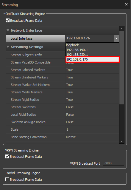
It is important to select the network adapter (interface, IP Address) for streaming data. Most Motive Host PCs will have multiple network adapters - one for the camera network and one (or more) for the local area network (LAN). Motive will only stream over the selected adapter (interface). Select the desired interface using the Streaming tab in Motive's Settings. The interface can be either over a local area network (LAN) or on the same machine (localhost, local loopback). If both server (Motive) and client application are running on the same machine, set the network interface to the local loopback address (127.0.0.1). When streaming over a LAN, select the IP address of the network adapter connected to the LAN. This will be the same address the Client application will use to connect to Motive.
We want the Clover and Motive machine connected to the same router, where in this case we can select the IP address assigned from this network. Keep a note of this IP address as it will be used when setting the data stream in the following steps.
Firewall or anti-virus software can block network traffic, so make sure these applications are disabled or configured to allow data transfer from Motive to the Clover.
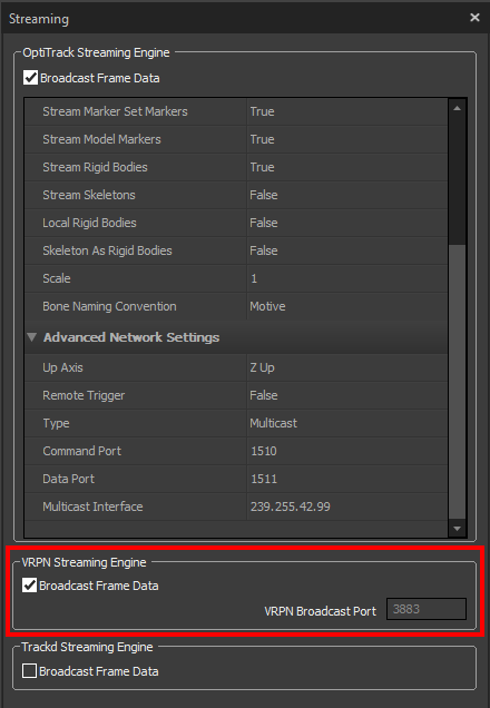
The data streaming method used in this tutorial is VRPN streaming. However, I implemented a UDP streaming method in conjunction with NatNek SDK that is more reliable and I prefer. Providing a brief tutorial in the future on this method is on my to do list. For VRPN streaming, follow these steps:
Note down the IP address given to the OptiTrack PC as it will be used when feeding pose data to the Clover:
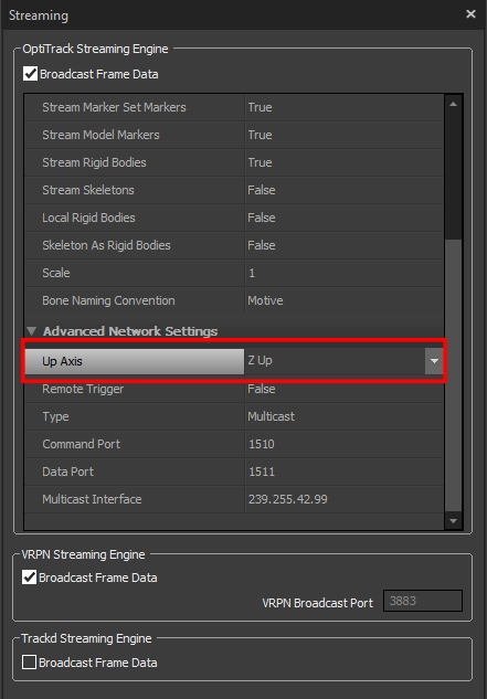
In the Advanced Network Options in the Data Streaming pane set the Up axis to be the Z-axis (the default is Y):
It is very important that you align the forward direction of the Clover with the x-axis of your motion capture volume before creating the rigid body in motive. This x-axis was previously defined when setting the ground plane during calibration (it can simply be viewed in the motive software). If this is not done, the external vision data may not fuse with the onboard pose estimate i.e. fusion errors. If it does fuse, the yaw offset between the drones body frame and motion capture system reference frame will result in the Clover being unable to follow set-points i.e. uncontrollable.
Last updated